The circuit described here, is a fsk modulator with output in the audible range. I build it as a part of a future project I'm thinking of doing.
Although I think there is an easier way of implementing such a function using a 555 timer chip, the first idea that I had for alternating the output frequency between to values was to change one of the resistors used in the basic astable circuit. Because I didn't have mosfets available at the time, I used one 2n3904 to act as the switch, toogling between the 2 resistor values.
On the picture below you can see the circuit that I designed (there are a lot similar on the internets)

T1 is controlled by SIG_IN which is the signal to be modulated. When SIG_IN is low T1 is "off" and only R2 is part of the astable circuit resulting, idealy, a frequency of f0=3.608kHz. When SIG_IN is high, T1 is "on" and the resistance between Vcc and pin 7 is R1||R2=1k resulting f1=4.810kHz (idealy) at the output pin. Duty cycle changes as well, but at the moment it's not a problem.
Implementation on the breadboard

Testing on the prototyping board

After first test on the proto board, there were spikes on the positive edges, so I added a 10n cap between Vcc-GND and then they were gone.
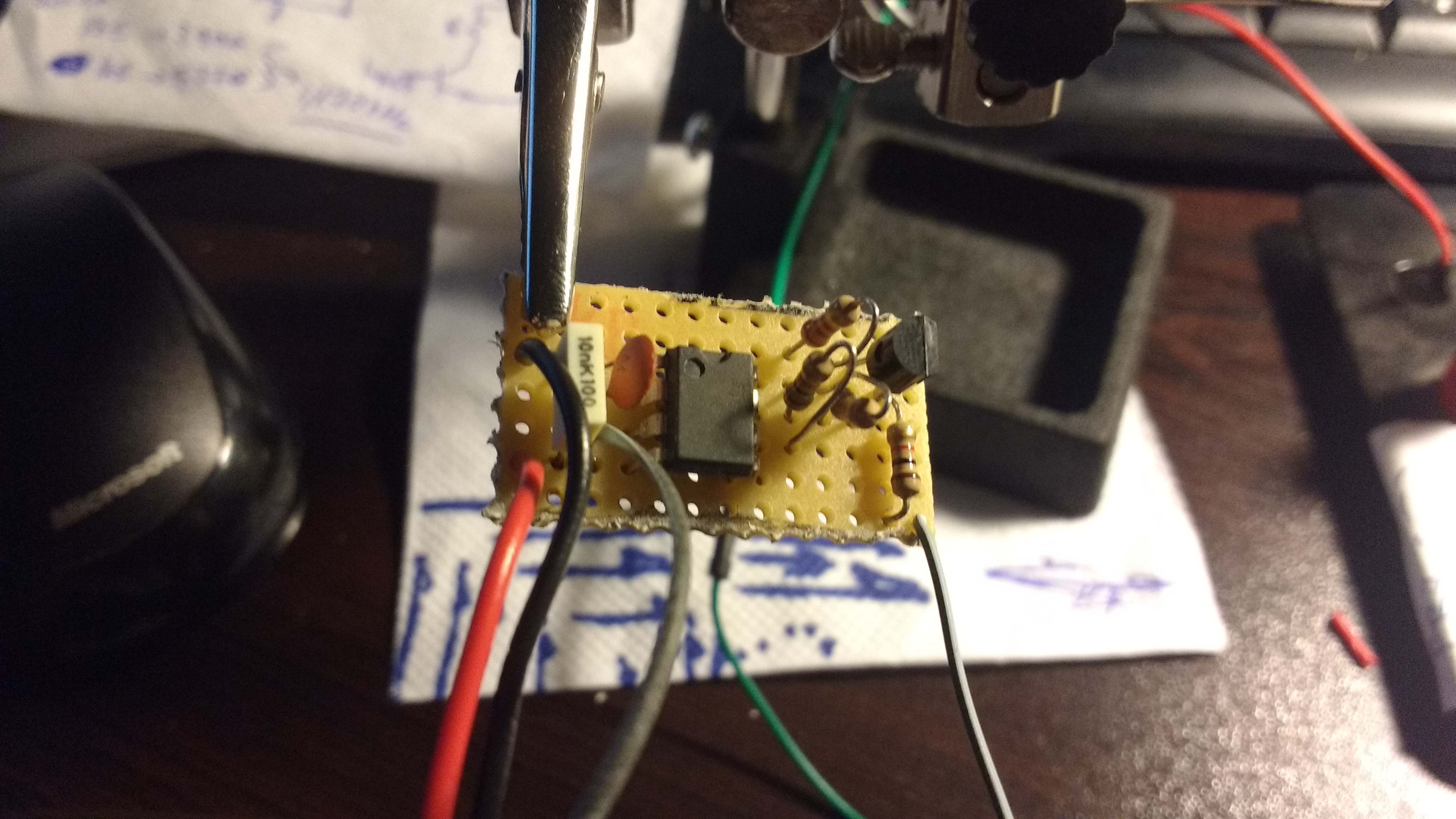
Finished Board without 10n cap

Under Vcc=2.8V it worked close to the calculated frequencies as you can see below
Output of the circuit for SIG_IN=GND

Output of the circuit for SIG_IN=Vcc

What remains to be done is to measure the maximum frequency of SIG_IN that the circuit continues to do its job.
Just for the fun of it, I connected the output of the circuit in an op-amp (lm324) configured as a voltage follower and on its output I connected ear phones. You can see a video of this below.Note: on the video I used higher Vcc so the frequencies are a bit off..