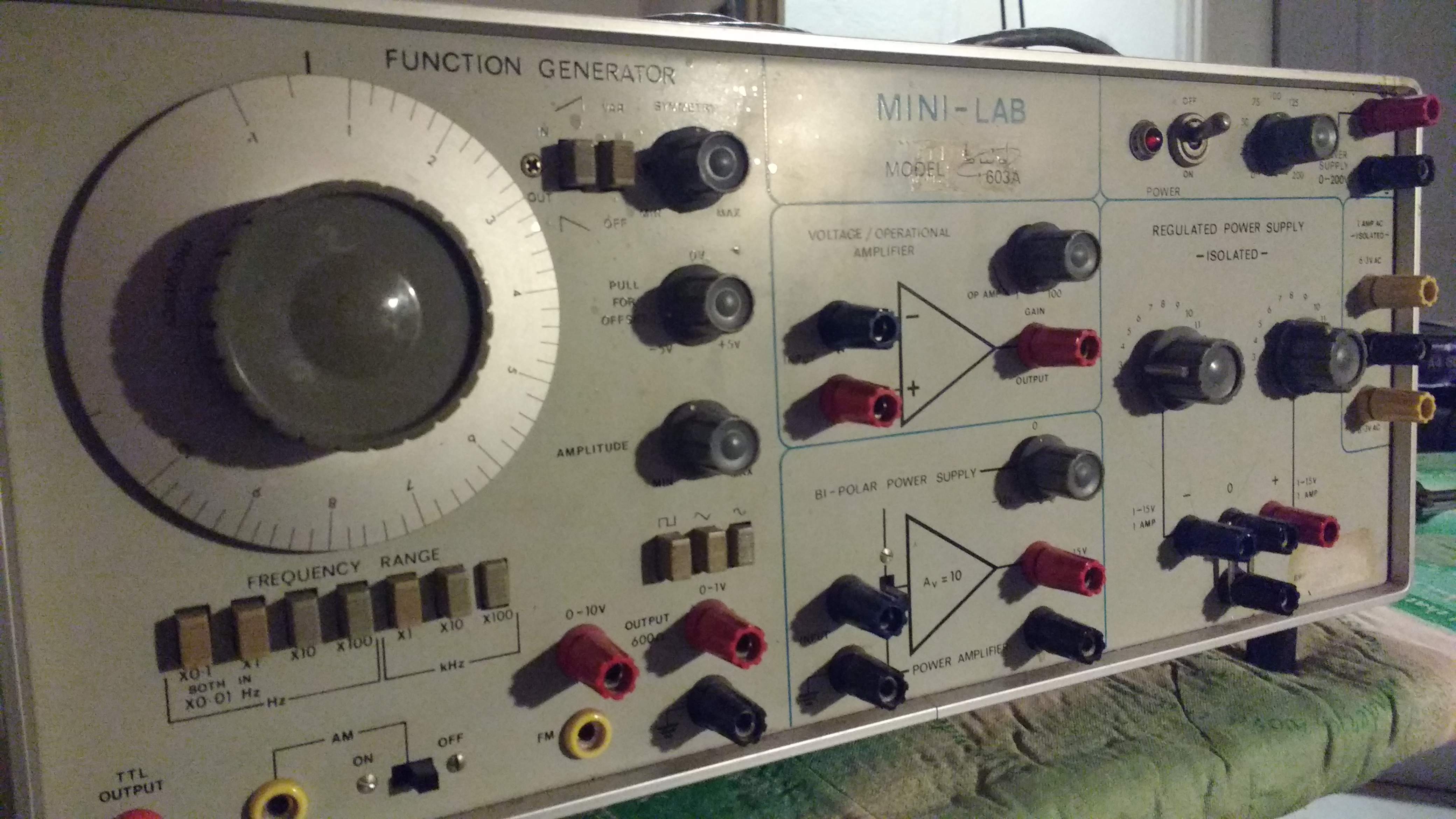
While looking for (relatively) high voltage power supplies, for experimenting with vacuum tubes, I came across this system on ebay and for about 90 euros I saw it as a bargain. It is one of those "complete laboratory" systems that are usually used in schools for performing lab excercises. The kit has a function generator, 2 op amp "break outs", a dual rail power supply (+/- 15V max) along with a convenient supply of 2 6.3V rails (a voltage commonly used for a tube's filaments) and an adjustable 0-200V DC supply which can be used as the HT supply. The function generator is capable of generating sine/square/triangle at a maximum frequency of 1 MHz and performing AM/FM modulation using an external signal as the modulating input. The unit, excluding the two op amps, was working fine and the only thing needed was some minor adjustments in both the power supply and the generator.
The first thing that I decided to test was the basic functionality of the generator. I plugged its output to the scope and scanned through the achievable frequencies and output shapes (sine/square/triangle). Taking into account the fact that the frequency selection is made through a multi turn pot I did not pay much attention to the offset between the "indicated frequency" on the frequency selection jog wheel and the readout at the scope. The problem that caught my eye was the clipping that occured in the peaks when a sine was selected as the output shape:

So, probably, something gets overdriven. After a quick search, I managed to find the schematics and conveniently enough...
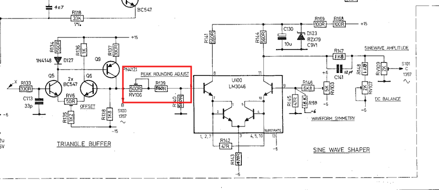
The task of locating RV106 was very easy due to the small amount of components in the board,

After a bit of playing with the pot, I managed to made the generator produce a sine that was good in the eye,

One may notice the difference in amplitude and average value of the output. That is due to the fact that I was playing with the amplitude and dc offset knobs before taking the photo. Having mentioned that, the offset needs a slight adjustment as well.
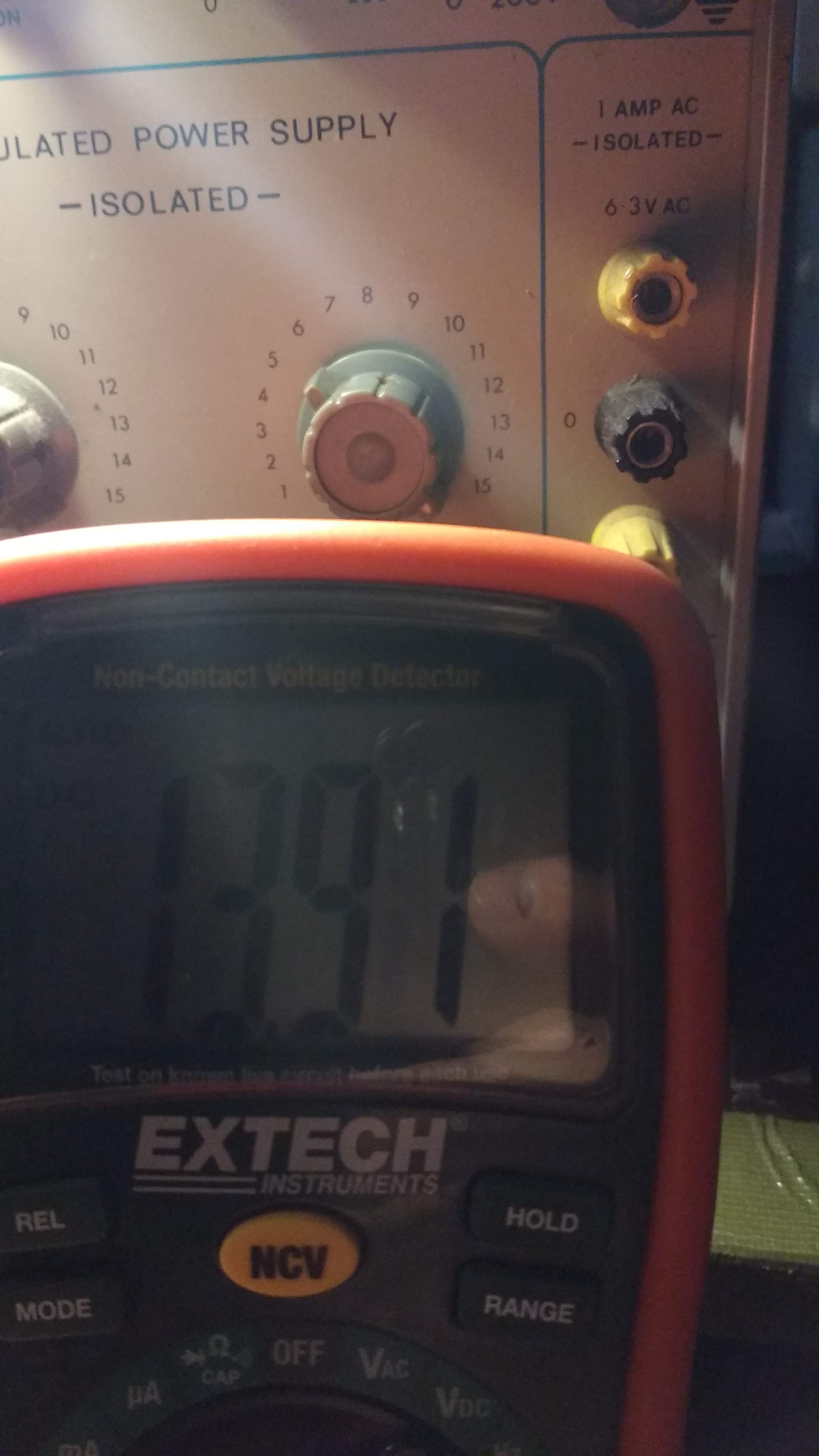
Having adjusted the generator it was time to move to the power supply. The high voltage and filament supplies were fine but the +/- 15V adjustable rails were not so good. When adjusted to full 15V output both rails were giving 12-14V (the "-" rail was giving around -12V and the "+" rail around 14V).
Readout of the "+" rail before adjustment
The power supply board had even less components so it wasn't necessary to search on the schematic for the appropriate pot. The designers were kind enough to mark the function of each pot in the silk screen,

...and after an adjustment on the pot...

After adjusting the "positive" rail, the same procedure was followed for the "negative" rail. I didn't bother checking the op amp break outs because the circuit inside was in a very bad shape. There were traces of magic smoke as well as burnt resistors, indicating a high current made a drive-by around that part of the circuit. Probably I will repair the circuit so... to be continued...