
Last summer, me and some other guys from university were in the process of cleaning an old robotics laboratory. When we arrived there there was a surprise. You guessed it, the old robot and it's controlling hardware were sitting there waiting for someone to estimate their age from the layers of dust on them. At the time I wasn't able to do anything on it as I didn't have enough time. But what I could do is find any documentation available regarding the system. The months passed by, 2015 replaced 2014 and I finally got time for playing with it. I resisted my urge to take it apart before powering it on and the results were not so good. The terminal was displaying weird dots and characters, and a perfume of an underlying magic smoke made its pressence clear. I immediately turn it off waited for about 20 minutes and did the same thing again, but no luck. The next day I decided to take it apart and try to figure out what was going wrong.
The controller
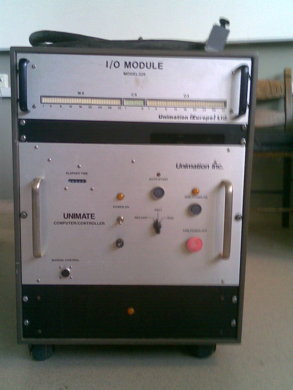
The controller of the arm comes in a rack with all the necessary hardware installed on it. It came with 3 units. The top unit is the I/O. This module is responsible (as the name suggests) for the (relay type/on-off) robot's communication with the outside world. For example you can activate via code a certain output at a certain point during execution, or you can read the state of an input. (todo: teardwon photos and talk about the relays)
The second unit is the computer controller itself. It contains the computer (cpu,memory,serial boards), the servo controller boards (each servo has its own controller board), a board which manages the feedback from arm's sensors (puma 200 arm has feedback only from rotary encoders and not pots, so it needs special calibration in contrast to other robots of the family), the power supply an finally the servo amplifiers.
This unit runs an operating system called VAL operating system/monitor. The VAL monitor is responsible for the control of the robot, and its commands come from the teach pedant, the system terminal, or from user programs. Programs are written in a language called VAL-2 and are made off high level commands to the robot arm e.g: MOVE BOX, where BOX is a (pre)defined location. When the system is powered on it asks to load the VAL monitor from the floppy (there are versions of the controller hardware where the val is written directly to the roms of the computer, this particular system is not one of them and luckily I found in the same room the floppy which had the VAL name written on it). Now its time to move on, and start taking it apart!
Back of the controller rack

On the above photo, you can see the connection between the i/o module and the controller unit via the blue ribbon cables. The little orange wires coming from the right thick one, are going to the terminal strips for interfacing the i/o module with other things. The left thick wire is the one going to the arm.
The big red button on the yellow casing, is used in case of an emergency and it cuts the power to the servo amplifiers. In another photo (see more photos link on the botton of the page) you can see another emergency button on the front panel of the controller.
Switches on top of the computer

The first of the above switches is the brake release, when its activated (on the up position) it releases the brakes of the motors. If the arm is enabled and you activate the release, it will automatically cut the power from the motors (I don't know if that is what it should do, i'll have to investigate it at somepoint...). The diagnostic leds, give you the health status for the servo amplifiers and the 40V line.The third switch just resets the computer. The second switch, halts the cpu. I'm guessing that it is connected directly to the BHALT signal of the qbus. If you power on the computer with the switch at the halt position it gets into debug mode. The debug is performed with the help of ODT which stands for Octal Debugging Tool (or technique, not sure). In that mode, the terminal shows a '@' and expects a memory address or a specific cpu register (e.g for register 0 you would type R0 or $0). Once you type the address you can type a '/' and it will show, next to the '/' the contents of the memory location/register you just typed. You can alter the contents of a location by doing the same thing only that time, next to the contents that the terminal will display, you will type what you wish to be written on the location. Using the letter 'G' instead of '/', you can jump in a location and execute a program from there. That way you can debug the system. Hints for pdp-11 testing
Computer back

The five connectors on the bottom right, are all serial connections between the computer and peripherals. Although in the same physical unit, the floppy disc and the terminal have seperate connections. On the upper left, you can see the big connector for the arm and the connector for the emergency button. The computer and the terminal are rated for 110 Vac but in my country we run on a sweeter juice, at 220 so the system needs a transformer which is the 3rd unit in the rack.
Side view of the computer

Upper cover removed

On the above picture you can take a first look on the inside of the computer. On the left side of the picture you can see the servo amps. The two huge caps are property of the power supply which is located underneath the amps. On the right side is the computer itself. The 6 boards in the middle are the servo controllers (one for each). On the lower right side of the photo, you can barely see the amplifier controller board and the feedback board. On the upper right side is the cpu along with the memory module and the boards which provide multiple uart communication channels.
CPU module

The processor module is a KDJ11-A. According to the manufacturer it was designed for use in high-speed, real-time applications and for multiuser, multi tasking environments. As you can see the cpu is contained on a pcb and it consists of two gold-plated chips. One of them "is" the control-path and the other the data path. The control chip is responsible for sequencing actions. It implements next address logic, interrupt logic etc. The data chip is responsible for command execution and memory management functions. Among other subsystems it implements registers,alu logic,mmu. The mmu is capable of handling 22 bit long physical addresses. It uses virtual addresses with 16-bit length. The relocation from virtual address to physical is done via the page address registers/PAR (there are 8 of them). The virtual address is spliced in 3+13 bits. The 3 bits select the PAR to be used and the remaining bits show the displacement within the selected page. The displacement is further divided in 2 sections. It offers 3 data/instruction spaces: kernel, user and supervisor. More information here and here
UART module

The module above is a camintonn CM-DLV11-J 4-channel serial interface board and it's an alternative/replacemnt to the dec's original DLV11J module. Its job is to convert parallel data received from the bus, to serial and send them to peripherals and of course perform the same job the other way around, periph->serial->parallel->bus. The dip switches in the middle of the board are used for setting the interrupt vector although the module has the ability to act as a polled or an interrupting peripheral dictated by processor commands. The jumpers between the 4 big chips are used for configuring the uart's mode, regarding data,stop and parity bits. The jumpers next to the right most chip are used fore setting the baudrate for each channel. More information here
So, when I turned it on, the terminal displayed weird things so my first thought was that something was wrong with the serial interface. To support that, the second time i turned it on I was keeping an eye on the display of the teach pedant, because I made the assumption that the pedant, as a peripheral and having the same connector with that of the terminal, was communicating with the computer via serial link. Et voila, the pedant was displaying rubbish. Of course that may meant that the cpu was sending rubbish to the serial module. So when I took it apart i removed first the serial board. I took a close look at it and nothing seemed to be wrong, no evidence of magic smoke were present. I didn't touch the cpu module at this point. I reconnected the serial module with its cables an put it back to its slot. I turn the thing on again and.. MAGIC, the thing was working, and it was displaying the odt prompt. At first I though that it still had a problem, but after playing with the switches on top, I got it asking for the val-floppy. I loaded the floppy, waited for it to boot, and finally I had manual control of the arm from the pedant!
ODT prompt (the date is a bit off)

After putting the halt switch to the RUN position

Teach pedant displaying related message

Unidentified module (probably another serial module)

The module on the above picture is at the moment unidentified. The photo doesn't help very much (due to its pure resolution), and I didn't had time for taking it apart again just to see what is written on it. The second time I took it apart, to inspect the memory module, I forgot to check this module and didn't had a camera with me to take any pictures. I want to take it apart again because one of memory module's batteries is in a very bad shape and must be replaced.
Finally there is some documentation online about the programming of these things.I have been playing a while with it, and there are some interesting ideas of things to make it do. UPDATE: There is a problem with the i/o (todo: add photos with disassembled i/o module). the computer doesn't recognize the ifsig command which is used for reading the state of inputs on the i/o module and that is a bit restrictive. That is an interesting problem because I can control the outputs of the i/o via the signal command but can not do anything with the inputs so...there will be a point in time were I'll take a closer look at it.
Turning the system on
Arm performing pick and place move