In the same place that I found the robot arm, a while after I found that system along with a hitachi monitor under a table. Both the system and the monitor were rated 110Vac so I couldn't test them...or could I? I remembered that the robot's controller had a 220->110 transformer, so I removed the back cover once again and I connected both the system and the monitor on the transformer (I was lucky enough and the transformer had exactly 2 outlets). First I tried to turn on the monitor but it didn't do anything, then I switched on the system but it didn't turned on either. I dissasembled the monitor first, grabbed my multimeter and tested the input fuse (which was inside a rubber sleeve, and directly soldered to a small pcb), the multimeter wasn't beeping. Not having any spare fuse with me, I went on the "scrapyard" of my university. There, there is a large number of old crt monitors and broken photocopiers. I knew that any monitor would have a fuse on its power supply. After a bit of searching and dismantling I came back with about 5 fuses. I don't remember the monitor's fuse rating but I remember that one of the fuses I came back with was exactly that and it was at the correct size to! So I desoldered the old fuse from the monitor and started to solder back the "new" (of course I tested it before soldering). My luck abandoned me at that point, because I overly "cooked" the fuse with my soldering iron, and as a result the fine wire of the fuse detached from the upper metal cup. To solve this, I desoldered the fine wire from the bottom cup as well, then I carefully soldered two wires, one at each side of the fuse's wire,I tested for continuity, passed it through the rubber sleeve and finally soldered it on the board. I turned on the monitor and it powered up! (Sadly I forgot to take any pictures of that)
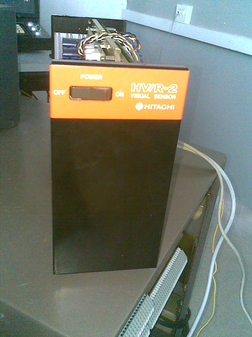
Vision Sensor
After fixing the monitor, I proceeded with fixing the system itself. I took it apart and the first thing that I tested was, once again, the power supply fuses.In that power supply there were 2 (maybe 3,I don't remember since a bit of time has passed from the time I played with this thing) fuses. One was burnt and I replaced it with one of the previously mentioned fuses. The size of it was ok, but the rating was off by 1 amp. So I took the risk (If the broken fuse was a result of something drawing excess current within the system, the results of my action would have a familiar smell on my nose).
The fuse holder of the burnt fuse (on the photo you can see the good fuse) on the right of the ac filter.

I connected it to the monitor, powered it on and it beeped!!! But on the monitor the system was displaying the following message

So, something was wrong with the system's memory. The system has 2 pcbs: one is the power supply (the left board as seen from the front) and the other is the main pcb (the right board). The memory chips are located on the lower left side of the main pcb. Under the memory chips was a battery. I removed it from the board and measured it. Surprise surprise, it was showing mV readings. The battery was rated at 3.6v, and it happened to have a 1 cell (3.7v) lipo. So I soldered some wires on the pcb and connected them to the lipo. On the next photo, you can see the new battery (blue, on the left of the photo), the wires soldered on the former battery place and the old battery (red, lithium-labeled).

Main pcb with wires connected to the new battery

After doing that,I powered it on once again and the following was displayed

The system seemed to work. It is controlled via a pedant (like a tv-remote,todo:add photo) and the navigation to the menus is done by pressing numbers on the pedant. After a bit of searching I was not able to find any info on the system which is a bit weird. As I mentioned earlier, my guess is that you connect a camera on it (it has 2 video inputs->you can connect 2 cameras) and somehow you "teach" it to recognize stuff. So I connected my camcorder on it and made it (there is an option in the utility menu for that and its called "camera monitoring") show the camera feed directly. It displayed nothing, well it was obvious that there were scan lines that were not there when you had nothing connected to the input,but no clear image as you can see in the next photo.

Camera connected to the system. (On the scope you can see the system's video output to the monitor)

The camera was on b/w mode, which meant that the output was b/w. However I hooked the camera on the scope and there was the color burst reference on the signal. I am not very familiar with analog video but I know that on a b/w signal there is not a color burst, just a black reference on the beginning of the scan line. The scope's screen was the following
You can clearly see the color burst.

For comparison, the b/w signal coming out of the system looks like this

So at the time I thought that that was the problem, so I borrowed a dome cctv camera which was b/w and I hooked it to the system. Again, nothing. The dome camera had color burst on the output as well.
Dome camera connected to the system.

Dome camera connected to the scope, you can see the burst on the scope's screen.

After that, I thought of connecting the dome camera directly to the monitor. The monitor was ok with camera's signal and it was displaying the camera's view.After that, someone may say that the system is the problem and not the camera(s) yea, but you don't know what sort of processing is done by the system to the input signal, and what the system expects on the input. So back to the system now, if you look closely to the pcb, you will notice that there are a bunch of pots scattered around on the analog side of the board (the side with video ins/outs). So I grabbed a screwdriver, I set the tongue at the correct angle and started messing around with them. Sadly, nothing seemed to had notable effect.
The next though was based on the fact tha the system was 110Vac. The thought was that both cameras were pal. What if the system is ntsc? Then what happens with the monitor? I haven't found a ntsc camera yet but I found a lab in our university that has the same system and I plan to pay them a visit. When I have an update I will write here about it.